In this project, I’ll take you through my journey of designing and building a custom MIDI DJ controller from scratch. Combining CAD software, 3D printing, and custom microcontroller software, I’ll show you how to create a fully functional device that seamlessly integrates both hardware and software—capable of controlling popular DJ software like Mixxx. This step-by-step guide offers a hands-on approach to constructing a personalized MIDI controller, making it perfect for anyone with an interest in electronics, 3D printing, or music technology. Disclaimer: Prior to this project I’ve never user any DJ controller!
Layout
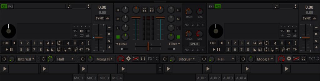
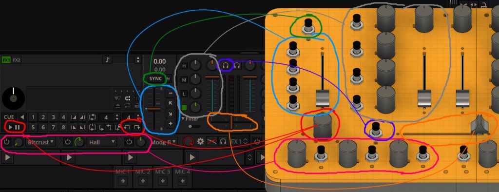
Woah a lot of buttons, knobs and sliders… This is the UI of Mixxx, the virtual counter part of the planned midi controller. As a first step, all the controls that I planned to use, needed to be selected and suitable parts ordered. Let’s focus on one side of the UI, as it is mirrored anyways. So I ended up with the following selection of UI elements, that I wanted to control:
- jog wheel – to seek forwards and backwards in tracks
- pause play tracks
- sync lock button to sync the speed of tracks
- temporary slow down and speed up
- slow down and speed up
- speed slider
- high, mid, low filter, including their mute buttons
- filter knobs and their activation buttons
- volume slider and gain knobs
- cross-fade slider
- headphones button to select which side is playing on headphones
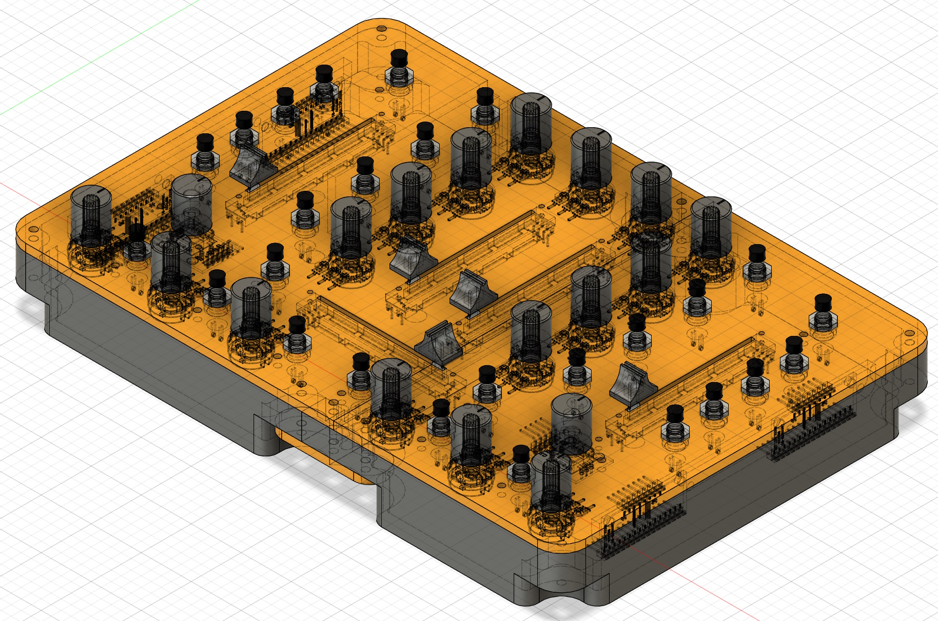
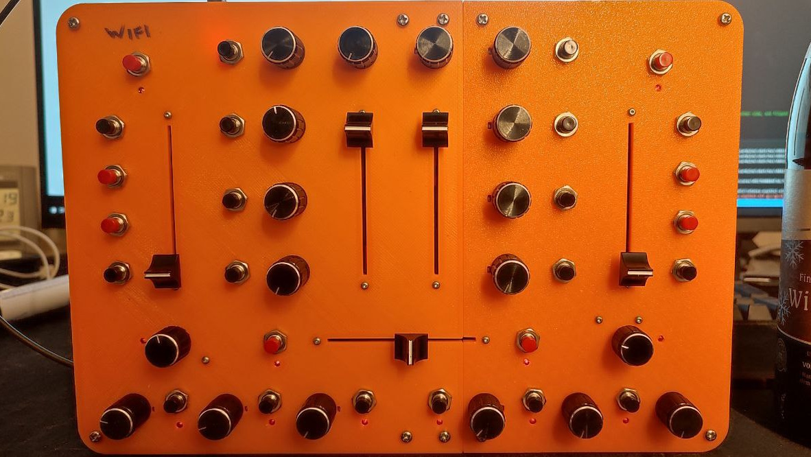
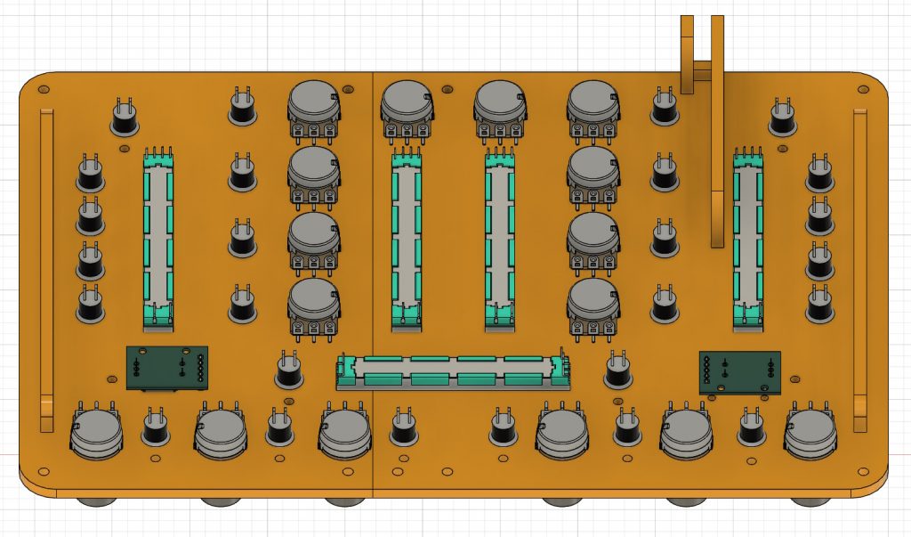
Here is the planned layout in CAD compared to Mixxx’s UI, side by side:
- 26 push buttons
- 16 rotary potentiometers
- 5 linear potentiometers
- 2 rotary encoders including push button functionality (in red)
- 12 LEDs
Efficient microcontroller wiring using multiplexers
Directly wiring all the components would have required a microcontroller with an impractical number of pins—around 65, not even counting ground and power connections. Fortunately, there’s a simple solution: multiplexers.
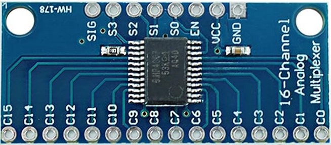
I used four 16-channel CD74HC4067 multiplexers to reduce the number of pins needed to interface with multiple components.
How multiplexers work
A multiplexer acts like a digital switchboard, allowing you to connect multiple signals to a single communication line. With these multiplexers, it is possible can connect up to 64 different signals (4 multiplexers × 16 channels) while only using 6 pins on the microcontroller.
Pin connection breakdown
- Enable (EN) Pins: These control which multiplexer is active
- Select Pins (S0-S4): Used to choose a specific channel (0-15)
- Signal (SIG) Pin: The communication line for reading or writing
Reading channels: step by step
Here’s the systematic process for reading all channels:
- Enable a specific multiplexer by activating its EN pin
- Use the S0–S4 pins to select a specific channel (0-15)
- Read the signal on the SIG pin
- Repeat for all 16 channels
- Move to the next multiplexer and repeat
Writing channels: LEDs
This setup isn’t just for reading signals. It works beautifully for:
- Reading potentiometer values
- Reading button states
- Controlling LEDs
By rapidly cycling through channels, you can control LEDs without noticeable flickering. The speed of modern microcontrollers and the persistence of vision makes this possible.
Additional component connections
Not everything needs a multiplexer. For instance, the two rotary encoders connect directly to the microcontroller, requiring only three pins each:
- Clock (CLK)
- Data Transfer (DT)
- Switch (SW)
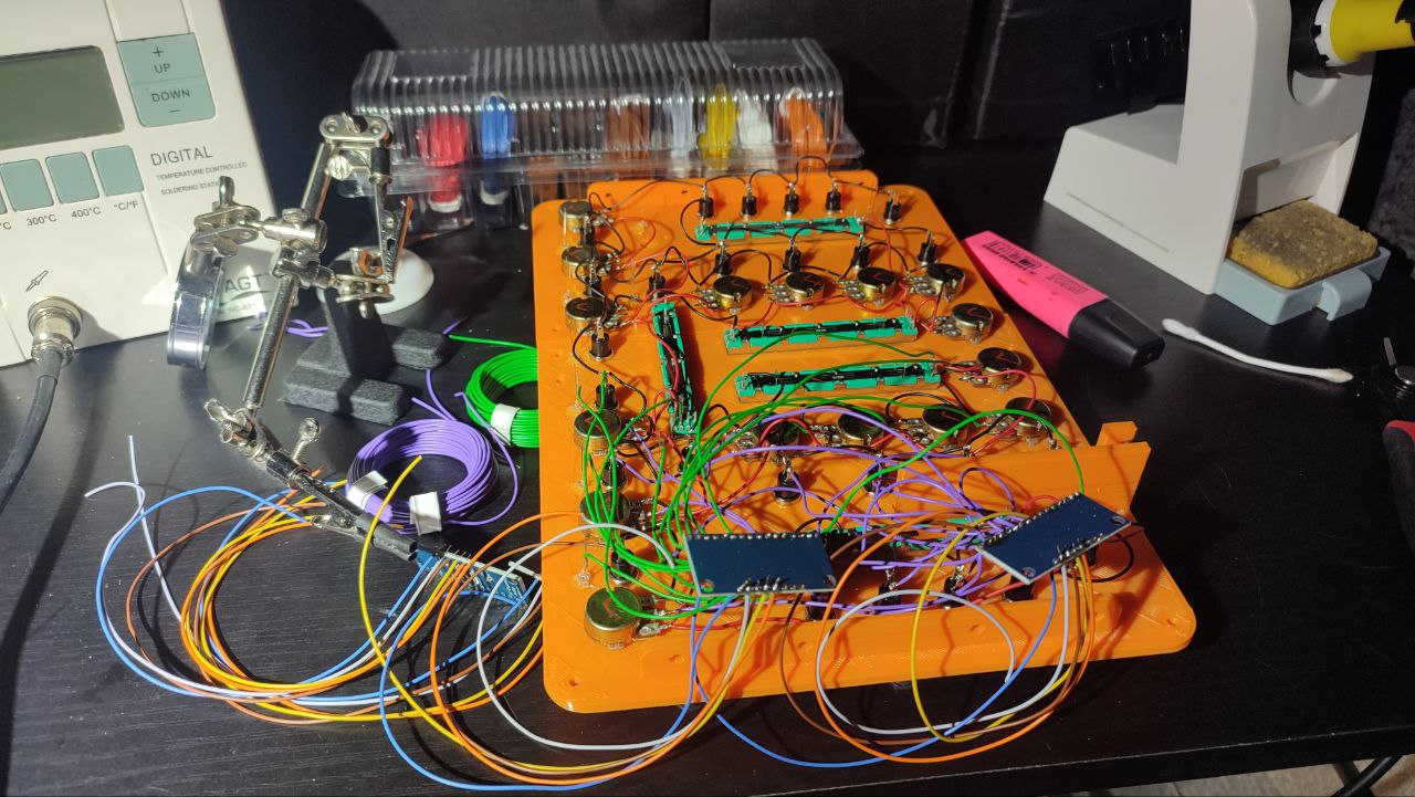
Wiring
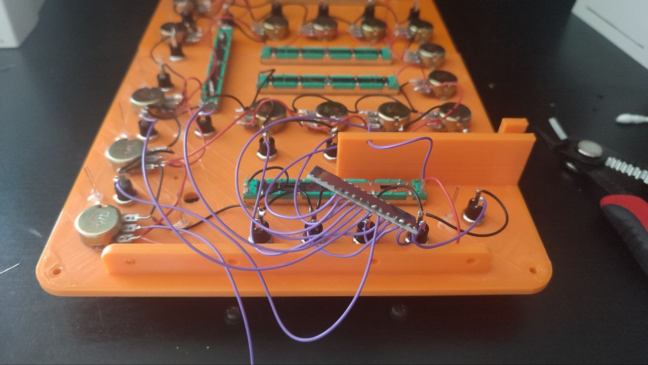
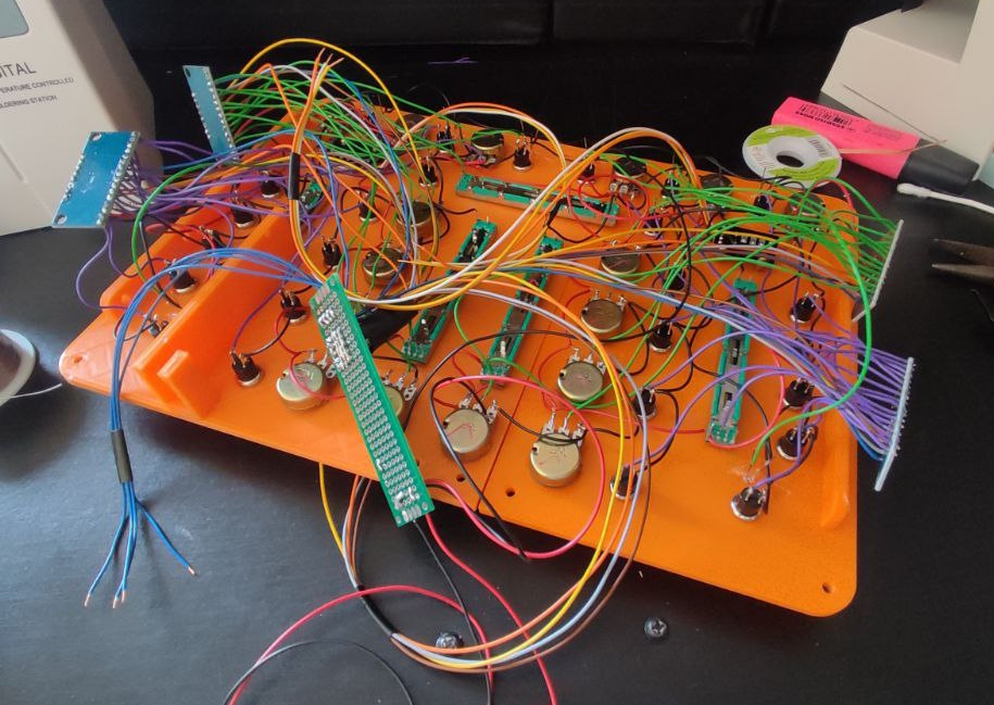
My wiring still got slightly out of hand, but the four multiplexer significantly reduced the complexity and pin requirements, making this project a lot more accessible. When designing complex electronic systems, always look for ways to reduce direct pin connections. Multiplexers, shift registers, and other expansion techniques can be game-changers. Anyways here’s a picture of the wiring. To simplify the microcontroller connection, a green prototyping PCB connects all the signal (SIG), enable (EN), and channel (C0-C15) pins of the four blue multiplexer boards, effectively creating a centralized wiring hub.
Microcontroller
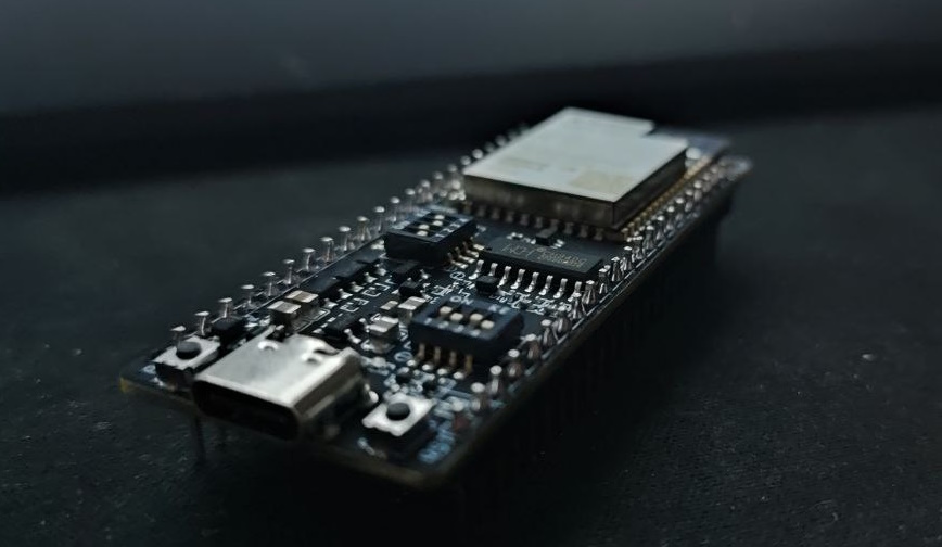
To power this project, I selected the ESP32-S2 microcontroller—specifically the T8-ESP32-S2-WOOR v1.1—which brings several capabilities to our design. This microcontroller is particularly well-suited for this MIDI controller project due to the following features
- Native USB functionality, allowing it to act as a MIDI class USB device
- Integrated WiFi for network connectivity
- Sufficient processor power to handle multiple tasks
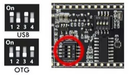
- Flexible configuration options through onboard dip switches
The dip switches provide a crucial flexibility for device mode selection. They allow to toggle between two USB modes:
- USB mode: Debugging and development
- OTG (On-The-Go) mode: In our specific implementation, this enables MIDI device functionality
This microcontroller’s ability to rapidly iterate through connected components while simultaneously performing signal filtering makes it an excellent choice for complex input mapping and real-time music interface applications.
The microcontroller’s dip switches create a programming limitation: USB mode is required for firmware uploads, while OTG mode enables MIDI device functionality. Once the microcontroller is built into the case, the dip switches aren’t easily accessible anymore. However, this isn’t a significant issue. The initial firmware can be loaded via USB, and subsequent updates can be performed wirelessly using the built-in WiFi through Over-The-Air (OTA) updates. This means you’ll only need a physical USB connection once to set up the device, with all future firmware updates happening seamlessly over the network.
Software
Here’s the repository with the code: https://github.com/AJ92/midi-slayer-one
Building the firmware should be done with the arduino IDE in version 2.x, and esp32 board manager in version 2.0.4. Version 3.x and newer do not work! Same goes for EspTinyUSB dependency. It has to be the one mentioned in the readme.
The microcontroller implements button debouncing and potentiometer value filtering to reduce analog signal noise and jitter. These signal processing techniques smooth out input signals but can introduce slight input lag. The filtering parameters are configurable, allowing users to balance signal stability and responsiveness according to their specific needs. By mitigating noise from analog inputs and multiplexing, the controller ensures more reliable and consistent performance.
OTA firmware updates are enabled by holding button b0 for 5 sec after connecting power via USB. All LEDs light up and the esp32 connects to the hardcoded wifi accesspoint. The firmware can be uploaded via any browser. After the update the esp32 has to be restarted. Disconnect and connect it again.
Calibrating potentiomenter center and end points is done by holding the button b12 for 5 sec after connecting power via USB. All LEDs start to blink. Move all potentiometers to their minimum, then to their maximum, and center them. Once all of them are centered, press b12 again, and the calibration is stored.
After wiring make sure to use the correct PINs. Adjust https://github.com/AJ92/midi-slayer-one/blob/main/midictrl/midictrl.ino to your PIN layout!
For Mixxx you can import the controller mapping midi-slayer-one.midi.xml linked bellow.
Pictures