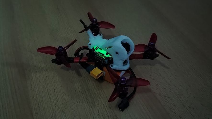
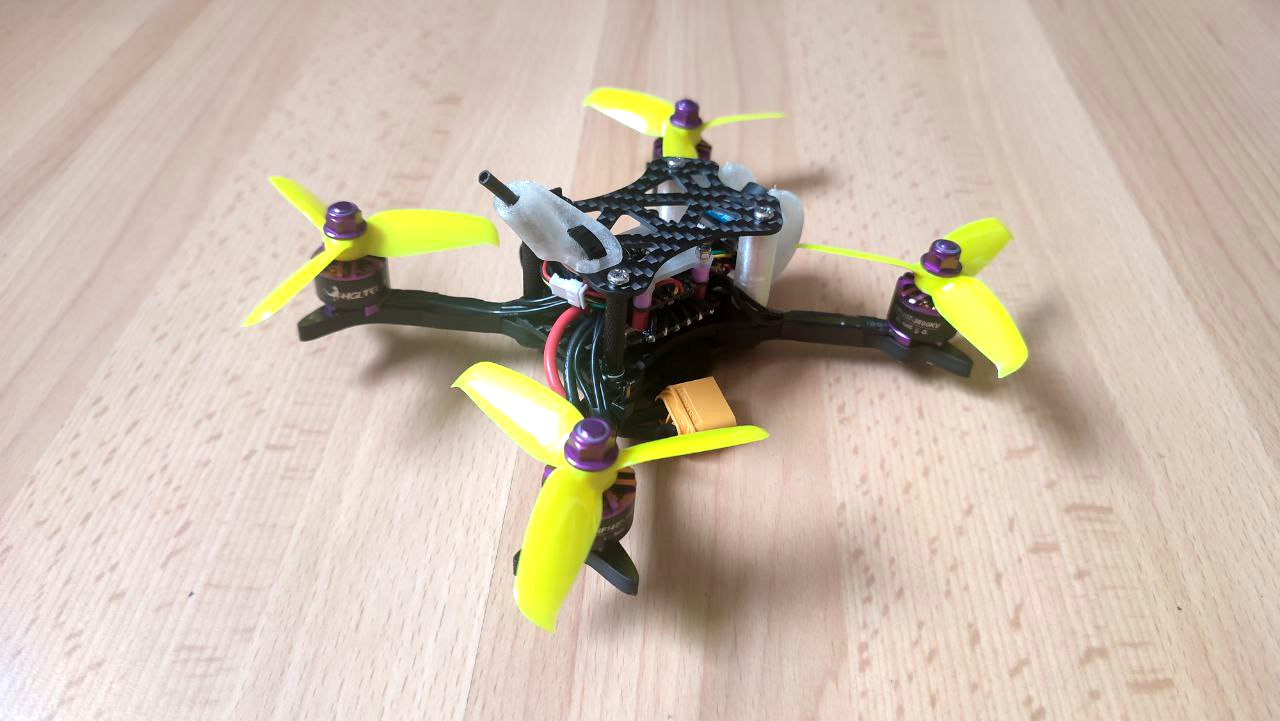
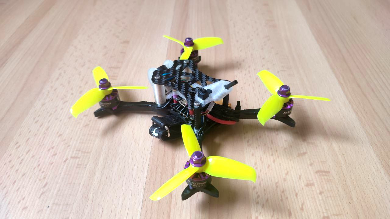
At the end of 2020 I started to fly quadcopters, and I got hooked! The freedome to fly how ever you want is awesome, but can also lead to damaged hardware pretty quick. My first copter was the HGLRC XJB 145 v1.2, which I destroyed a few times within the first 10 flights. RX loss has lead to a bad crash where I’ve broken one of its arms. This means I had to wait a few weeks for a replacement bottom plate. I also had problems with the VTX antenna after it got pulled a few times. Little did I know, as this damaged antenna destroyed a handfull of VTXs, but the worst part was the frame, which was a bit tricky to assemble. It was rather cramped, and every time you put it together something wasn’t fitting 100% correct.
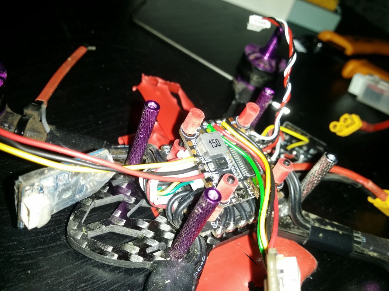
After another bad crash in a tall tree and a recovery a few weeks later, the copter was in a bad shape and I decided to improve the disassemble/assemble process by using a single TPU canopy, instead of 3 carbon fiber plates ( 2 side plates + top plate + 4 standoffs ).
Design
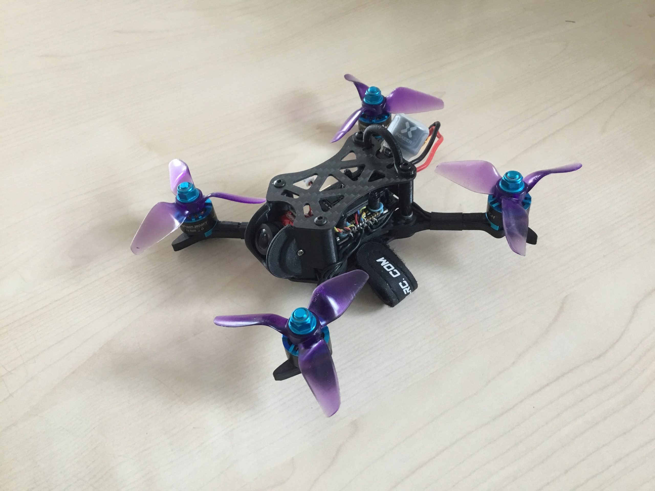
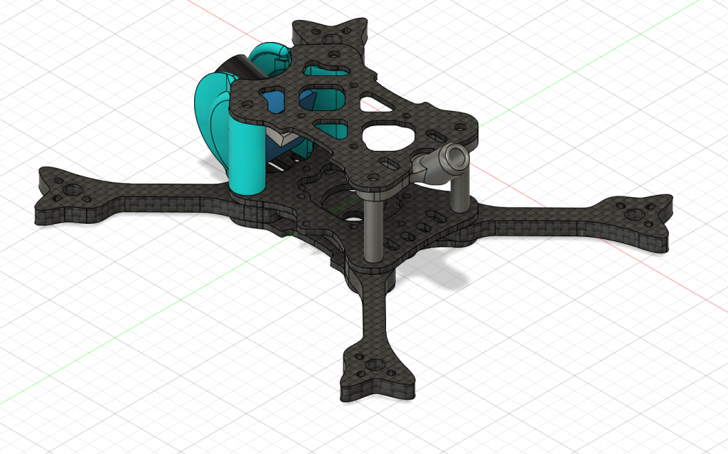
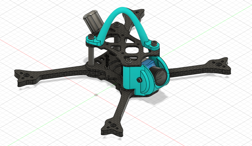
Now that the copter is discontinued and the replacement parts will be unavailable soon, I decided to design my own 3″ frame, which should be extremely durable, a bit more roomy inside, and easy to assemble / swap out broken parts. I started by scanning the remaining XJB 145 frame plate I had, so the mounting holes for the motors and stack would be perfect. The frame was streched a bit to have more room inside and fit a bigger camera, which was a problem bofore and lead to the tall TPU canopy to clear the propellers. In addition to that, the most important update was durability. I wanted to get away from the 3mm thick bottom carbon fiber plate and use 5mm thick independant arms, so the arm mounting concept of the five33 switchback pro frame got adopted.

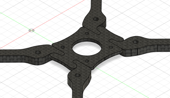
Each arm is held in place by one single screw, which goes through a bottom plate, the arm, a top plate and screws into a pressnut on the upper plate and into a standoff. Those screws are m3 now, to withstand crashes better and a single screw is enough here, as the arms fit like a puzzle into the center wiggle plate, and can not rotate anymore. A lower and upper carbon fiber plate is pressing them thogether and the arms are sitting perfectly tight in frame. The 2mm thick center wiggle plate has 4 screws for the stack and at the same time holds itself to the upper plate of the arm sandwich. The 3mm gap between the wiggle plate and the lower plate is reserved for a lipo strap.
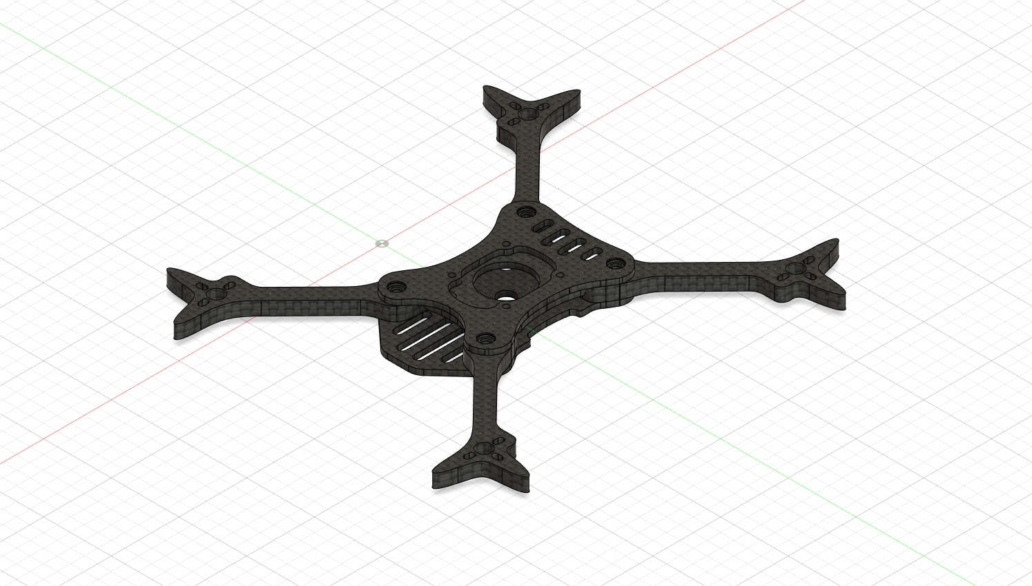
The bottom plate has a front grill to provide a little bit of impact protection for the camera and holes and space to mount additional hardware like a buzzer or a RX. The upper plate has also a small grill which can be used to ziptie a capacitor if needed.
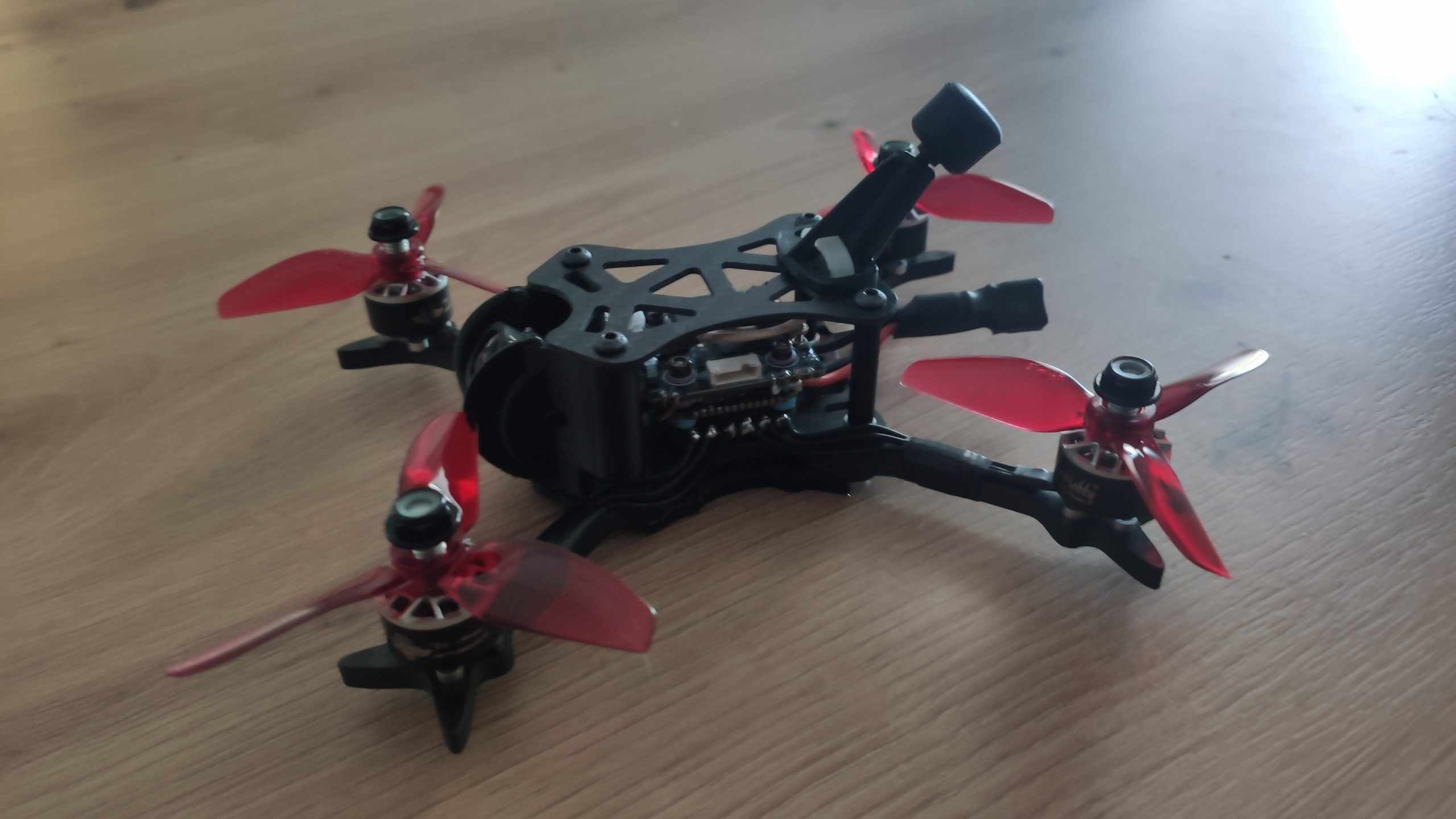
Two spikes for the arms should protect the motors from impacts. Also the arms are now a bit thinner and have a cross section of 6mm x 5mm. This reduces blocking of the airflow, but still provides enough strength to survive a few crashes.
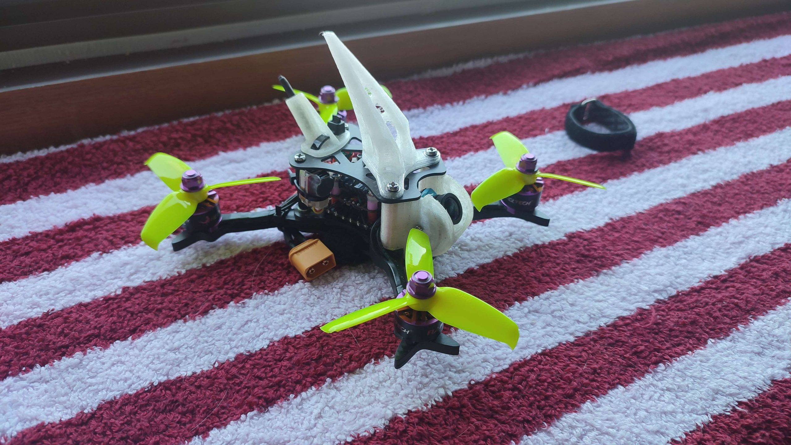
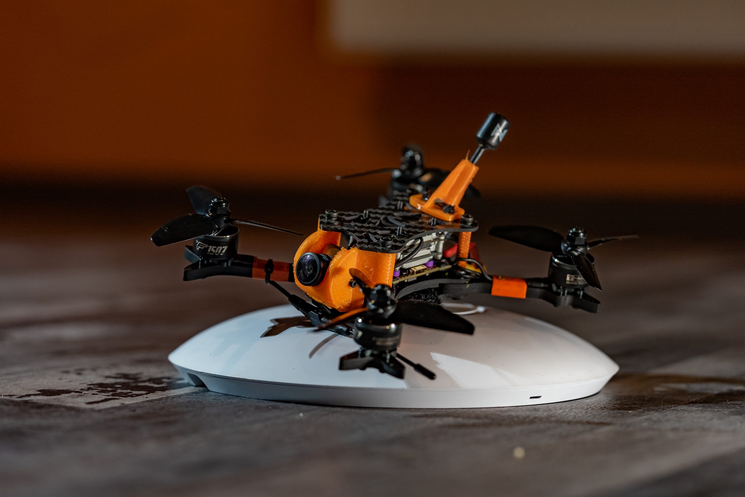
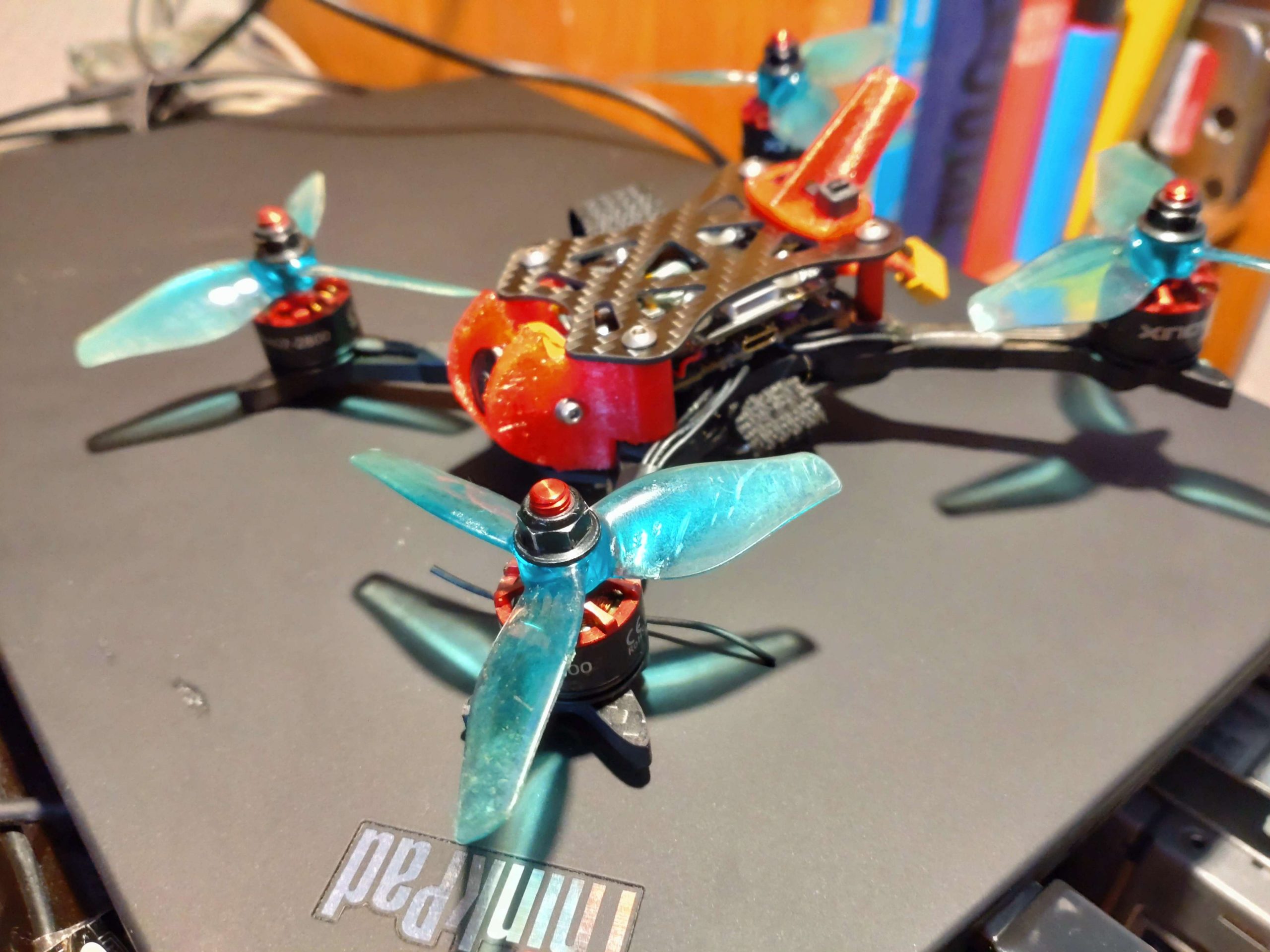
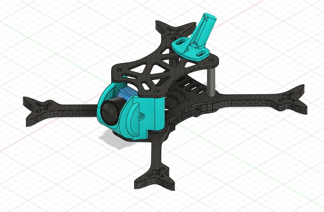
A top plate, camera and antenna mount complete the vtx-slayer-one. The mounts are 3d printed with TPU and are flexible enough to survive crashes without breaking immediately and still protect the camera and antenna. The top plate has holes to mount additional hardware like a camera.
First prototype
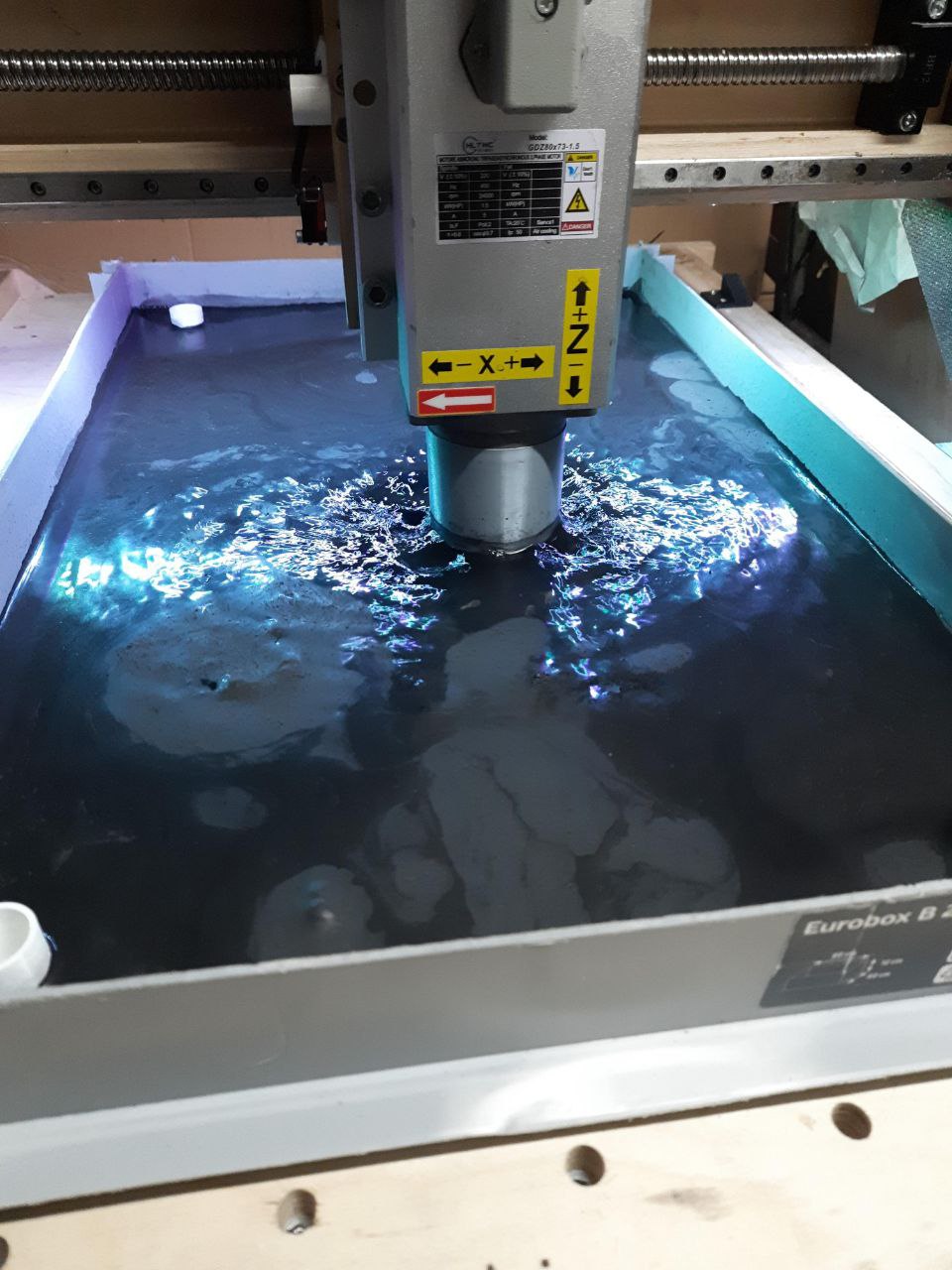
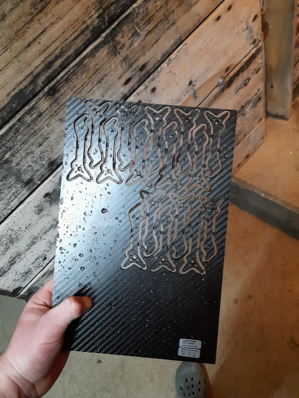
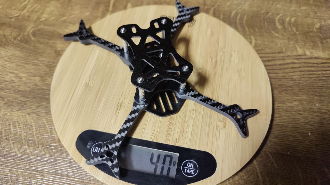
The final cad design was sent to a fpv buddy with a cnc milling machine for final checks of holes and tolerances. ~43 grams should be the total weight of the frame with m3 screws and aluminum standoffs.
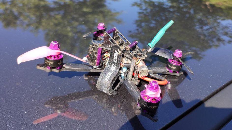
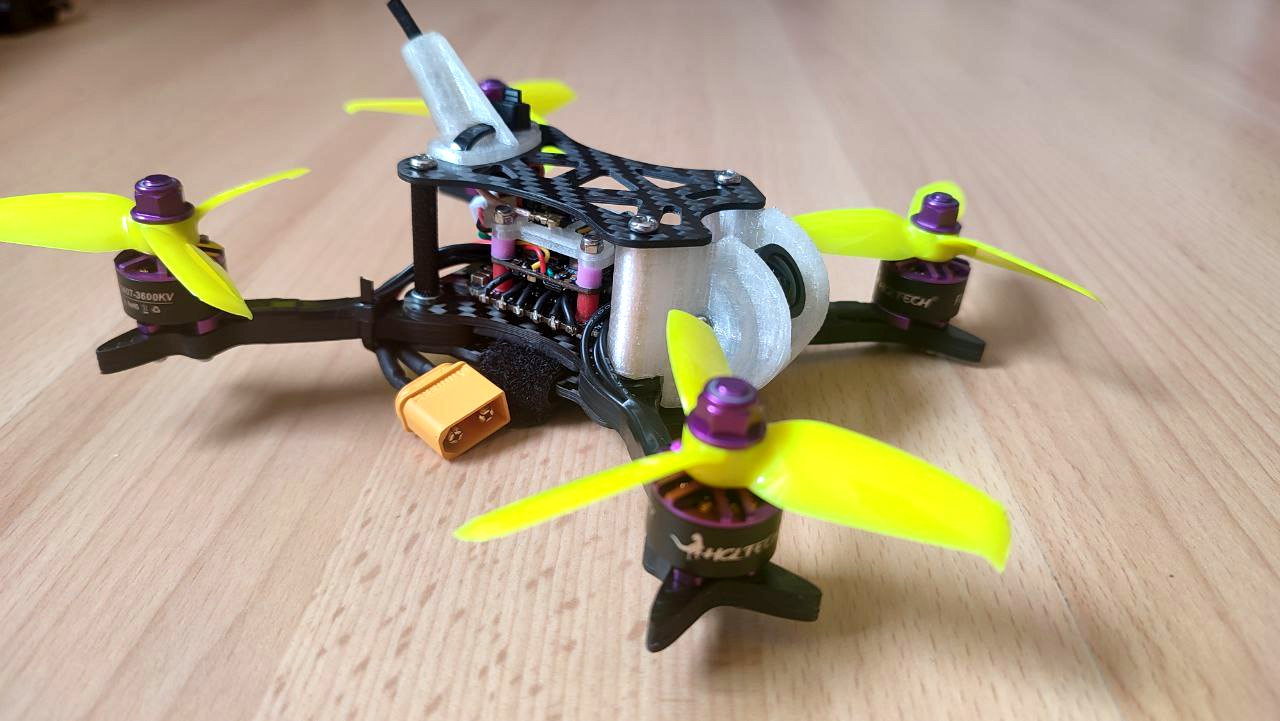
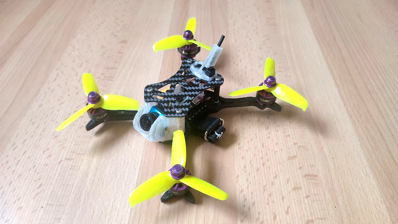
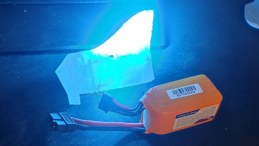
By adding new spare motors, a runcam phoenix 2 camera, the original hglrc stack ( esc + fc ), a new elrs happymodel EP2 RX and a new EWRF E7082VM VTX, the build was complete. Total weight with a 850mAh 4s lipo is ~280g. On the software side the rx received a fw update, and the vtx was flashed with openVTX. After fixing motor directions and configuring betaflight the 3″ vtx-slayer-one was ready for its first flight.
Assembly
Parts:
- 1x topplate 1,5mm
- 4x arms 5mm
- 1x top sandwich plate 2mm (for arm and stack mount)
- 1x bottom sandwich plate 2mm (for arm mount and stack mount)
- 1x armconnector 2mm (center wiggle plate for arm mount)
- 5x M3x8mm
- 5x M3x16mm
- 5x pressnuts
- 16x M2x7mm motorscrews
- 4x M2x20mm stackscrews
- 8x M2 (nylock)nuts for stack screws
- 1x TPU cam mount
- 1x TPU dipole antenna mount
- 4x M3x20mm standoffs (15mm for a slammed build)
Cost ~46€
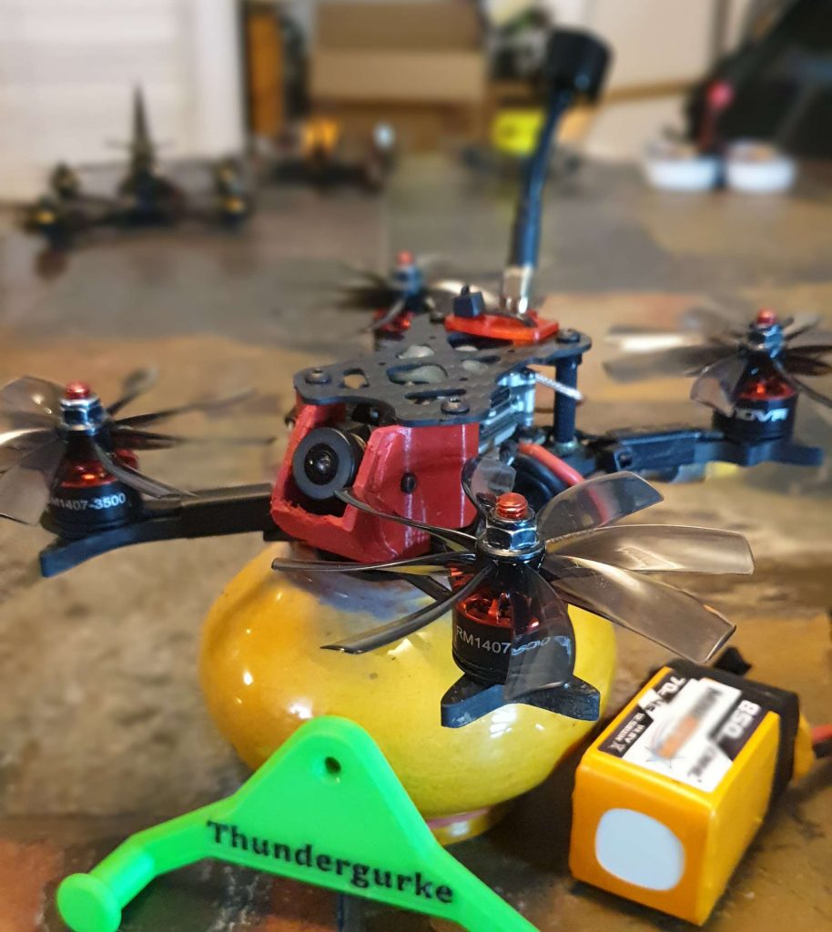
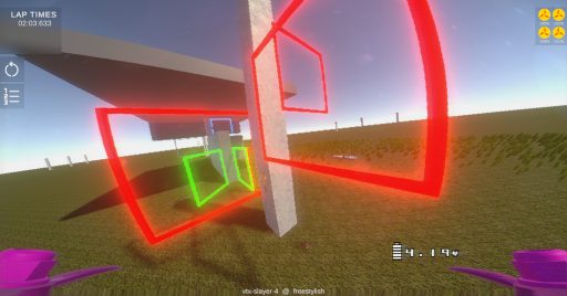
The 4″ variant on the race track
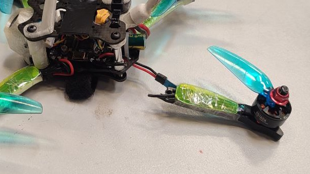
The 4″ frame with 1407 3700KV (4s) motors performed decent during DCS Aichtal. Rear motors became hot, but that’s the only problem i experienced. Arms and the frame in general experienced no noticable damage, even after a few midairs. Over 55 packs where flown during the event, all on one quadcopter.
After an upgrade to 1606 3300KV (4s) motors over 36 packs where emtied with the same quadcopter that I used during DCS and the same overall reliability could be observer. No broken motors, no broken arms. I also used the same old props.
Update 1.3
- increased arm strength around the motor holes
- added 25.5 x 25.5 mm stack/AIO mounting holes
- added 20 x 20 mm mounting holes to the top plate (e.g. vista mount)
- added new vtx antenna mount
Update 1.4
- 4″ arms
- caddx vista antenna mount
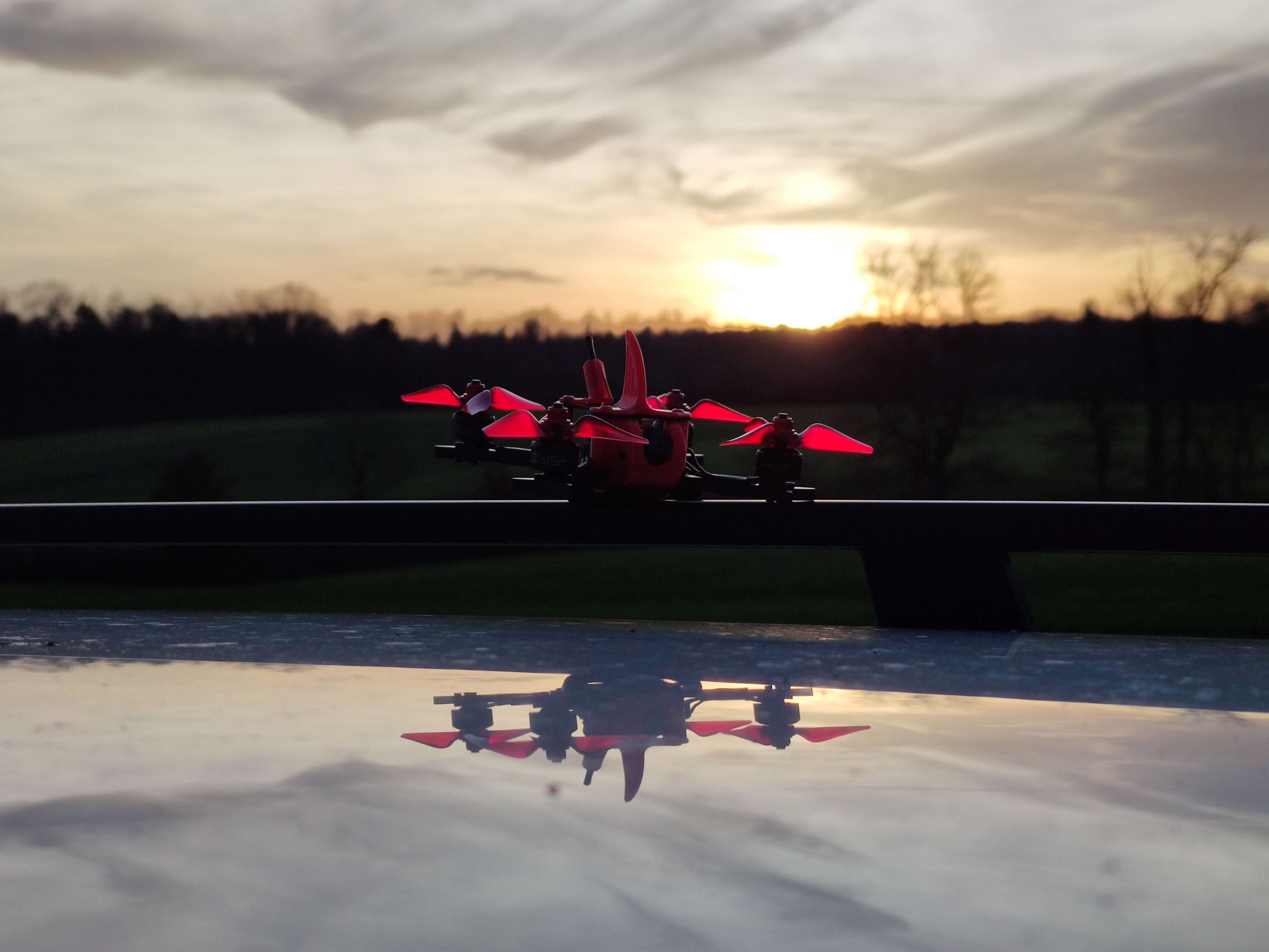
Update 2.2
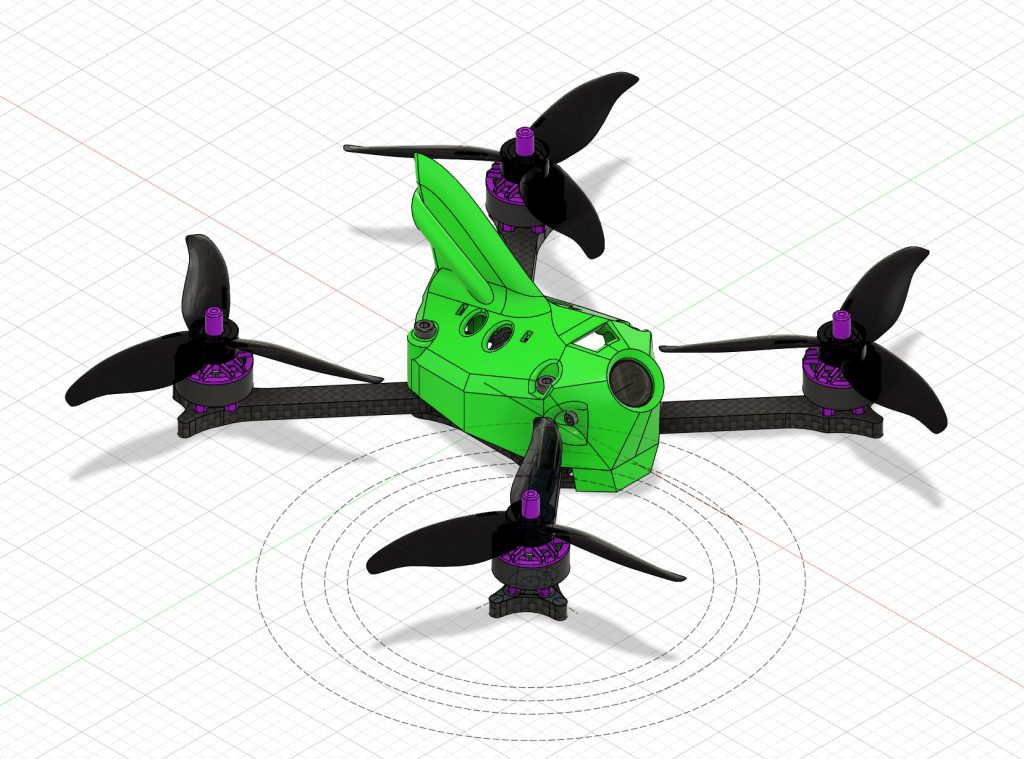
- TPU canopy
- amost-true-x arm layout
- removed press-nuts, thick enough standoffs are enough
- parametric arm length
Update 2.3
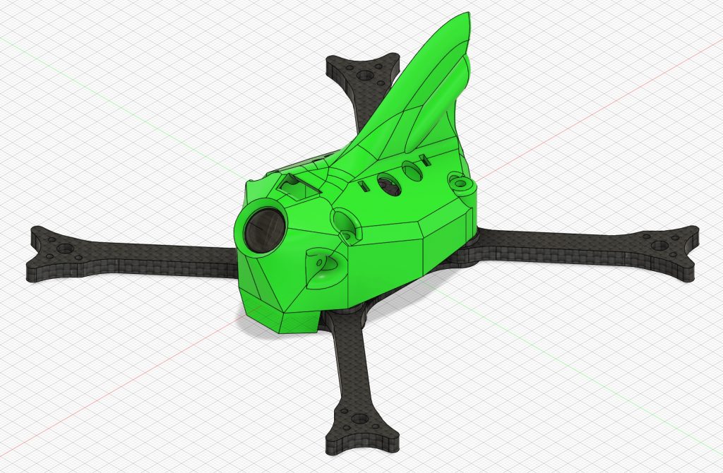
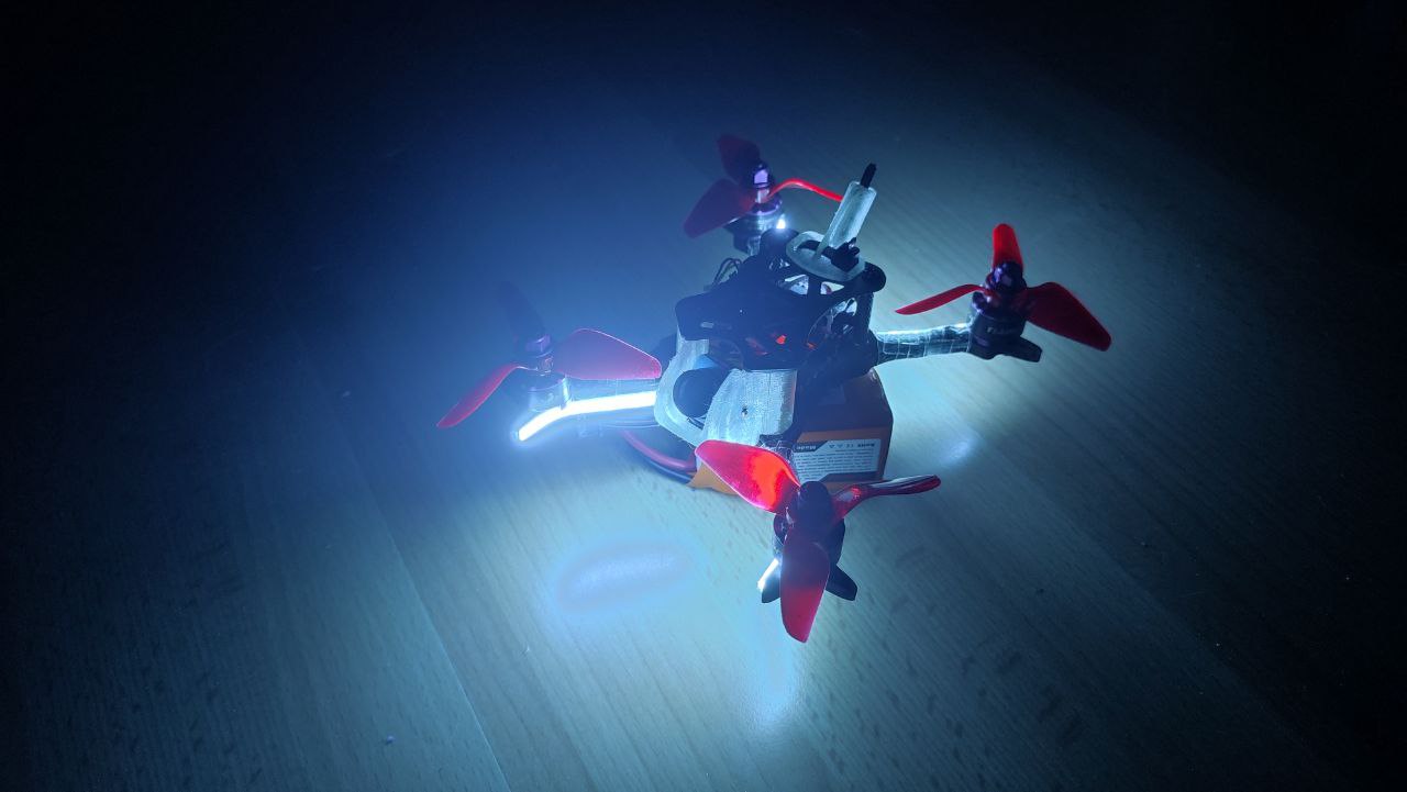
- added 5cm LED strip insert in canopy fin
- added strength to fin base
- changed canopy air holes
- stronger arms around m3 holes
Split canopy
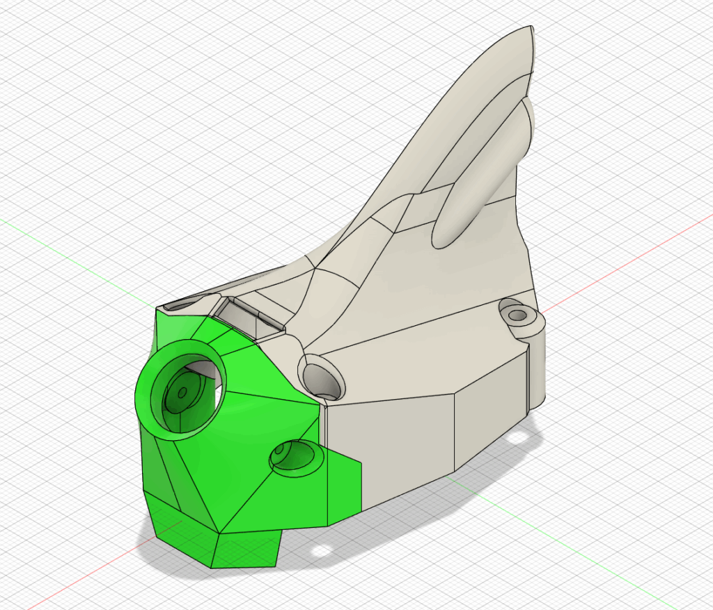
Cam part is split from rest of the canopy. This allows the fin to be printed upright, and has the benefit of easier access to the electronics, without removing the cam all the time.
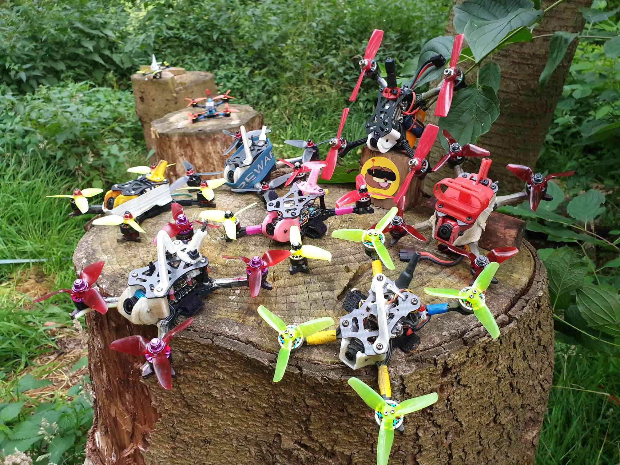
Happy pilots 😀